I was going to begin this post with the line, “Amplifiers are more trouble than they are worth,” but thought such hyperbole (which reminds me of my favorite example- “money is more trouble than it is worth.”) might be better left to poetry and in any case, in order to be heard, one has to have a little power.
The transverter itself has an output of about +15.25 dBm. That isn’t going to cut it- I wanted to have something in the full watts range to initially begin and will move up to the big Motorola amplifier after I get some air time with my baby system first (and eventually convert the big amp to work with my setup- more on that in the coming months/first of the new year). The problem becomes: how do you go from 32mW to, say, 5 watts, without too much trouble?
I asked the W1GHZ yahoo group what they were doing for driver amps, and one fellow mentioned the seller rfextra on ebay. He sells both a PA module and a development board (separate) which would be capable of doing what I was looking for. He sells the modules under the name “SHW5151.” Apparently, these modules have a Motorola pedigree- but of what kind and sort I cannot say as I am unable to locate a data sheet on this particular module. I’m certainly not picking on rfextra, as he supplies some links to schematics (and also supplies parts placement pictures) from a Motorola handheld in which this unit was used; you aren’t flying completely blind here. I’m happy with my purchase and left positive feedback. I would also point out that he sells a different module that also covers 33cm, but I have no knowledge or experience with it. I can tell you that I did not include the R3 resistor, as it wasn’t needed. And for the four inductors (L1-L4), I used two different sizes (0805 and 1206, as called for) of 22 uH.
As an aside, the W1GHZ Transverter group on Yahoo! is probably one of the best microwave groups around. There is very little noise and everyone is quite helpful. I scan the Mw list and the UK and VK microwave Yahoo! groups for information all the time- a very cursory review, believe me- how any one person keeps up with all the traffic must be someone who is either retired or a microwave junkie. That said, I really focus my attention on any posts from the W1GHZ transverter group whenever they show up in my email box- it’s usually that good. Especially when W9SZ speaks up. Zack is a treasure trove of information and he is always happy to share!
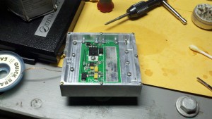
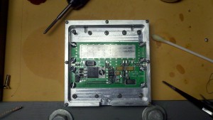
When I first began this part of the 902 W1GHZ transverter project, the module is not yet put down on the board, the board is populated with all the components and also has been fitted into its aluminum enclosure, as seen here:
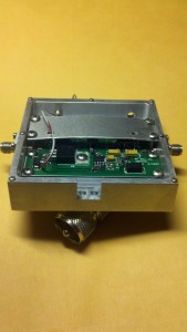
When finished, with the very generous help of my Elmer K4CSO, the driver amp looks like this (minus cover):
The SMA mounts were drilled, tapped and installed. It has been plumbed for power, as noted by the wire coming off the regulator going to the external connector. The board, when finally set, used thermal grease on both the ground plane and underneath the module itself in order to mitigate as much heat as possible (actually, a great deal of the grease bled through the thru-way’s drilled into the board- care was taken to make sure the correct amount was smoothed over and used- one of the few cases of “less is more”). The bar set across the top of the module (the module underneath, I grant you, is difficult to see) is used to make sure that the module stays flush with the board- also incredibly important for heat transfer. Removing as much heat as possible is critical to the longevity of this module and I will eventually have to mount a fan to the underside- it runs that hot! Why go to all the trouble to build this if you aren’t going to take care of it?
Once the construction is taken care of how you see fit, which hopefully includes some manner of heat dispersion, one’s attention should turn toward the actual biasing of the module- the matters of voltage and current. According to rfextra, the module should be calibrated and reviewed, “Around 4-5V, monitor the current when(sic) increase the bias voltage: at low RF input like – 20dBm, stop when current is about 1.4-1.6A.” I didn’t have this information when we began to tune the amp- poor preparation on my part- and we simply ran out of time. However, a conservative approach got us to nearly the same place the instructions did, so all was not lost.
After placing some current on the device, it did not self-oscillate, which is a great sign. This means there is no RF escaping somewhere to induce the device to oscillate itself. We started driving the device around -20dBm and stopped around 0 dBm. We got about 4.4 watts out at this point and were hesitant to go further without proper biasing instructions (people are claiming 10 watts out of this module at 12 volts- I’m not interested in running it that hard). We did not pass one amp of current for biasing- which is not enough current as per the instructions, though we did hit 5.3 volts- which is beyond the upper end of the instructions I later received. So, we are lucky we didn’t destroy the component, but it also looks like we aren’t going to get too much more out of it, either. A little more tweaking will get closer to 5 watts, which is all I will need to drive the Motorola amp mentioned above. Of course, if I drive the big amp a little less, that’s not a worry, either. I’m not looking to wring out as many “deebees” as possible at the risk of destroying what I’ve already achieved. As it stands now, there probably isn’t much more tuning to be done and I am very happy with how the module turned out.
Now the question becomes one of how to attenuate the transverter output to feed the amp at around 0 dBm. If it isn’t one thing, its another!
