There are many factors that determine good circuit performance. Proper design techniques, careful part selection and the attention to detail when it comes to assembly of a device are the three chief concerns of any electronics endeavor. But that is ex nihilo- upon what corpse is this creation to rest? In the same way that bodies have dominate sides or particular faculties, so too does the enclosure around which an electronic creation is encased. Microwaves are their own little creatures, after a fashion, and what you may find from one circuit board sitting on the end of a couple of attenuators, conjoined with the DC blocking adapter which then leads into the spectrum analyzer, can be completely different than what such a board, similarly attached, might produce when it is enclosed, and enclosed in the proper way.
I happen to know this through experience- which, so far as I know, is always acquired “the hard way.” In my case, I was attempting to wire up my transverter boards to my radio in order to see if it was functioning. I didn’t have any luck hearing any signals, mainly because I wasn’t properly set up to hear any, and in any case, it was late, I was tired and one loose wire screwed everything up when it energized the transmit section with the wrong voltage. I caught it pretty quickly but not before the white smoke escaped and I thought I had blown it up. What a way to go to sleep!
So, I contacted Charles, K4CSO, and asked if he could help. He graciously offered to see what, if anything, was malfunctioning with the transverter. As it turns out, apparently nothing is wrong and I caught the overvoltage in time. What was more interesting was the performance of the W1GHZ LO. Paul writes in his paper “902 MHz Transverter for the Multiband Rover,”
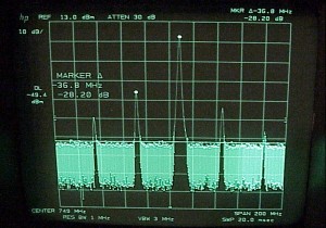
“The revised LO board with the combination filter works very well, with a 756 MHz output of +7 dBm, perfect for driving a mixer. The spurious outputs at 36 MHz away on each side are at least 30 dB down, and all other frequencies are more than 40 dB down except for a strong second harmonic at 1512 MHz.”
In this photo, you can see the harmonics Paul was talking about, and yes, they are ~36MHz spaced from the center frequency and approximately 30 dBc as mentioned.
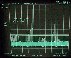
Above is a photo of a sweep from 10 MHz to 2 GHz. As Paul stated, the LO works as advertised. But it is dirty. Very dirty. I was curious as to why this is the case, as I would like to eventually use this transverter with some power- garbage in and garbage out- and being a good amateur I would prefer to have a cleaner signal. As I understand it, there is some overlooking of dirty signals the higher one goes in the bands- since no one is there and construction techniques being what they are, you aren’t likely to have a complaint when you are one of the few on the band!
However, that doesn’t answer the question of why there are so many harmonics. Charles informs me that such even spacing at such a small frequency multiple (in this case, ~36 MHz) is very likely to be the 36 MHz crystal oscillator that is located on the LO itself. One guess is that the signal out of the oscillator is getting into main LO signal via the large ground plane on the bottom of the board. It’s possible, too, that somehow the signal is getting mixed in one of the MMICs. It is also possible that once enclosed the transverter may act differently. In any case, I wasn’t terribly concerned with this until we put the W7BAS synthesized LO on the analyzer.
Confession time: After reading my post regarding building my W1GHZ transverter, W7BAS offered to send me one of his LO’s, gratis. I accepted. I’ve decided to write this review about it and will include the W7BAS LO inside my transverter. This review wasn’t solicited by giving me a LO and is completely independent of whether I got it freely or not. I realize I’ve spoken about the W1GHZ LO at great length; you will have to forgive my lack of brevity in this review in the interest of full disclosure- which whether I paid for something or not would, I hope, be the same. Also, the reason I am rejecting the W1GHZ LO isn’t because it doesn’t meet its published specifications- its because I’ve now got something that is much better. It should also be pointed out that there is the caveat regarding whether this LO was enclosed or not- as mentioned at the beginning, whether some board was enclosed or not so could make a significant difference in the measurements that are collected. As both were tested in the same way, one could argue that neither has a testing advantage over the other and would perform the same way in the same enclosure.
From what I’ve read, many people originally didn’t care for synthesized local oscillators because the phase noise was simply too high. However, cost is always the main issue, and with synthesizers lowering the cost of microwave LO’s, the telecom industry moved towards this technology without hesitation. This technology was cheaper and cooler to run. With less heat meaning less waste, the cost goes down further. While it might not have been at the time the most elegant solution, it was certainly the most expedient one. Today, the phase noise continues to decrease and there is now wide acceptance in microwave circles, and elsewhere, of synthesized LO’s.
The W7BAS LO drew 40 milliamperes and is designed to take a 12 volt source of DC power- something the W1GHZ transverter is sorely lacking. When put on the spec an, the frequency readout was incredible- 755.999 MHz. This is probably intentional (the goal was 756 MHz)- certification shops tend to always under certify some device by just a smidge in order to account for voltage/power differences between the lab in which the item resides and the actual shop that does the certification (and I believe there are other reasons for this in which I am not competent to articulate; I could very well be wrong about this point and could have misinterpreted what I’ve read, so do please be aware of this).
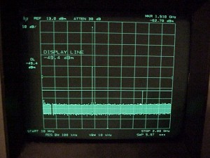
Like the W1GHZ LO, the W7BAS device also had a second harmonic around 1510 MHz. The main signal output was around 8.5 dBm, as sent from W7BAS. The second harmonic, unlike the W1GHZ second harmonic, was not just -30 dBc down- it was more than -60 dBc, as seen in the following photo:
 You will also note the lack of harmonics. This signal is, in the vernacular, “so fresh and clean” that it honestly couldn’t be practically better. If it was, I’m not sure what benefit would be achieved (this photo was a 10 MHz to 2 GHz sweep). Other than the second harmonic, there are no other harmonics of any consequence. This means that the signal made by the transverter wouldn’t be all over the spectrum (especially with the amplification issue looming in the future) and would be quite clean. In fact, it may be one of the cleanest on the band!
Considering the purity, but not in any religious sense, of this LO how could you not switch teams from the W1GHZ to the W7BAS? Admittedly, there is a price difference. The assembled W7BAS LO costs $89 bucks plus shipping. The other LO costs, all components in with the board and you assemble it yourself, around $25-30 bucks depending on shipping and parts costs. Why the price difference between two items that do the same thing? Well, look at the pictures. One does its task much better than the other. Will it matter in the long run which you use? I cannot say as I cannot speak to your needs or environment. Nevertheless, I would argue that the extra dollars are worth it because you have a cleaner and more precise signal. With a more precise signal, the less likely it is you have to tune around due to frequency drift, and the less of that you have to do should equal less frustration and effort. Who doesn’t love that?
I wholeheartedly endorse getting on the synthesized LO bandwagon and can’t think of a better driver than W7BAS.


