Driver Amplifier for W1GHZ 902/3 Transverter

I recall reading in the recent DUBUS magazine that something every VHF+ user could use was more power.  Naturally, everyone could use more power!  This fact escapes many people who run a barefoot (the all too common 100 watt) transceiver as their main rig.  Many HF users believe 100 watts is the starting point; of course, there is the QRP bunch who do a lot of communicating with a great deal less power.  Nevertheless, there is a large difference between what is QRP on HF and what counts for low power in the microwave domain.  Additionally, there is also a large difference between what counts for QRO between HF and uWave spectrum, as well.

The transverter, as measured so far, puts out about 32mW.  That’s just not very much-  it could get lost in the coax!  So, the plan is to build an amplifier that will take this output and turn it into something respectable (and not so hard to work for the other station!).  Also, I would like this all to fit in the same box- that is, I want the transverter to be plug and play with at least +1 watt output with the xverter boards, switching, sequencing and at least one amp.  After a couple of queries, I found something that I am hopeful will do the job.

A fellow on eBay is selling both a PA module and PCB board for a 5-10 watt (depending on how it is powered and biased) amplifier.  Ultimately, I will be using this to drive another amplifier, but for now, I’m just trying to get my signal above the microwatt level!  As I’ve not yet put mine together, I can’t say I recommend or that I dislike the seller.  I should have the unit built in the next couple weeks to a month or so; if everything checks out, I’ll vouch for the guy and give the sellers name.  The more curious and adventurous will have already looked up this information in the W1GHZ transverter group and will have found some driver amplifier solutions therein.

In other news, I feel like I am getting closer to a container for the xverter project.  After a back and forth email missive with W7BAS, he mentioned that I should check out Context Engineering.  (Also, while Bruce said he was not currently working on any 10 GHz project, he did say he “had some ideas” regarding a transverter.  Stay tuned folks!)  I like the boxes and different enclosures that CE has; that said, not sure what is going to be right for me.  Charles, K4CSO, talks about the solutions to these difficulties as “3D thinking.”  Wish I had more of it.

W1GHZ 902/3 Transverter Measurements and Build Notes

My 33cm W1GHZ transverter is assembled!  However, it isn’t a fully functional transverter because I do not yet have a complete sequencing system in place.  That said, the transverter and LO boards are assembled and plumbed.  I am continually on the hunt for the right kind of enclosure to use for the entire bit of kit and hope to have something soon.

Recently, with the kind help of Charles, K4CSO, I was able to have the device tested and get its measurements checked.  I don’t have the ability to check anything as I have no test equipment, and so I am very thankful for Charles to take time out of his day to lend a hand and expertise.  I was surprised by the results- mainly that they worked at all!  I don’t have a great deal of experience with surface mount soldering and often was concerned that I had cooked some part or other.  Turns out everything works fine!

Considering the cost of these kits, one is getting a new band for not a lot of money.  I secured the transverter boards and parts for $48.  With connectors, switch, sequencer, power parts and eventually some sort of enclosure, I imagine the entire project will cost me $100.  The same sort of thing (recognizing that there are significant differences between the two and that I’d rather have the DEMI if I could afford it) from DEMI would cost over $200 for the kit, and closer to $300.  The next comparable 902/3 transverter kit is from W7BAS and is currently $199 plus $6 for shipping.  So, like I said, you are getting on a new band for not a lot of money- but how well does it work?

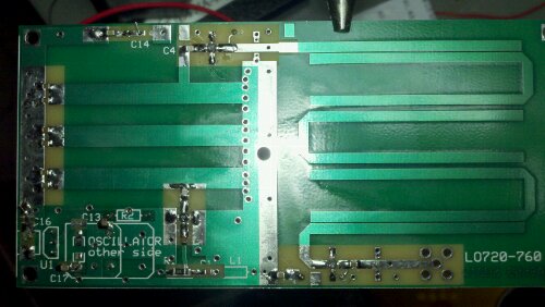
I put the LO board together first.  I decided that the best way to approach this would be to solder all the capacitors and resistors in place and then move on to the more delicate MMICs, crystal oscillator and voltage regulator.  This worked very well; if I had it to do again (and I will for my 1296 board), the only difference would be that I would solder the PCB to SMA (coax connector) first.  It appeared to take a lot of heat to get the connector warmed up and as a result it transfered a lot of heat to the board.  If you put this connector on first, you won’t run the risk of cooking the nearby MMIC.  And speaking of MMICs, I used the MAR-6 and MAR-1 from Minicircuits as was listed in the parts sheet by Paul Wade.

After applying some power (the +12 → +8 volt power plant was built using an LM7808 bolted to the ground plane), the current limiter said that the board drew 82 milliamperes.  Not a lot of current!  The LO output was +6.68 dBm, right where it should be for the +7dBm mixer on the transverter board (which had to be jumpered to reach the LO; I used a small piece of brass stock you can get from most hardware stores to jump the trace).  What was odd, however, was the frequency itself was not as close as I would have liked- the LO’s output is 755.985 MHz, off by 15 kHz from the goal of 756 MHz.  Doing a mild heat test of the crystal revealed that with an increase in temperature (unmeasured; used a heat gun), the crystal drifted another 10 kHz and landed at 755.975 MHz.  A better crystal oscillator would be closer to the desired frequency, as the Cardinal one that was supplied had a stability rating of +/- 100 ppm- they make them down to +/- 5 ppm in this particular form factor.  Eventually, even the hobbyist will have some sort of synthesizer to do the heavy frequency (timing) lifting that was once the domain of the crystal oscillator (you should really check out Andy’s, G4JNT, website for some synthesizer projects).

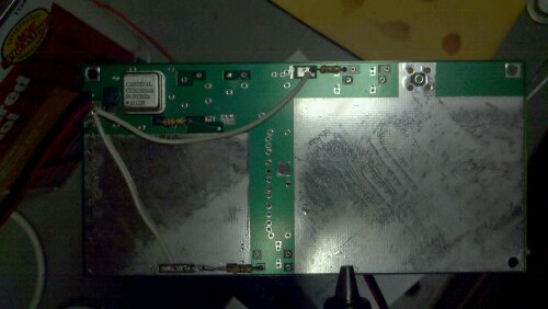
The transverter board itself was fairly easy to put together.  I would warn other folks to mind where you are putting the power supply capacitors for the T/R circuits, as you will want to drape some off the edge, so to speak, and make sure that the wire you want to use is in the right place and soldered down before you put in all the caps.  Alternatively, you may want to place them on the bottom of the board.  Here again, it is better to think of the major parts (plumbing and power) that have to fit somewhere first and then worry about where the little stuff is going to go.

I was pleased that the transverter put out +15.25 dBm (or, approximately 32 mW).  The TX side of the circuit took 187 milliamperes and the RX side of the circuit 120 milliamperes.  The 1 dB compression point (or more formally, P1dB) was at -2 dBm.  So, at least for my transverter, I need to attenuate my radio to -2 dBm output drive in order to avoid saturating the circuit.  Here, I used the following MMICs: A1=SGA3586Z, A2=MAR-6SM and A3=ERA-5SM.

The weak spot in this transverter board design, other than no consideration for built in power on any board that uses +12V input like most do, are the filters.  PCB filters aren’t nearly as tight as something one might otherwise procure from Mouser, but certainly will be at a higher cost than using the hairpin PCB filter.  Here again, we are confronted with price versus performance.  For what I am trying to do, I’ll be able to get by- but for those who like to hack around and make something more than what is given, I believe there are 900 MHz bandpass filters to be had that could tighten up the transverter without doing too much looking.

At the end of things, I’m pleased with the boards.  If you want to try to add a band cheaply, but not expect perfection from your price, I think you have found the right kind of kit.  I can only think of two improvements I would like to make: (1) at some point I’m definitely going to insulate the crystal with some Styrofoam and (2) may even build some shielding over the PCB hairpin filters.  With these two ends tied up, I should have a fairly decent way by which to get on 33cm!

OS X 10.6 Snow Leopard USB/Serial Connector for Xastir/APRS

There seems to be a lot of misunderstanding regarding what kind of USB/Serial adapter to use for OS X and Xastir.  There are two answers: use either a FTDI device (which requires some amount of effort if you are continually plugging in your TNC into different USB ports; but who does this, really?) or a Keyspan one.  I favor the Keyspan because I had one to use, it’s drivers worked the first time they were installed and because it is very rugged.  Also, using the Keyspan is easier, because each USB port is aliased to “/dev/tty.Keyspan1”.

What this means is that, no matter which USB port you plug the Keyspan USB/Serial Port adapter into, you can always use the “/dev/tty.KeySerial1” address in the Interface Control panel of Xastir.

While the nerds get all hot in the pants about how you could just as easily use an FTDI USB/Serial connector for Xastir, what they fail to mention is that you must use the “ls -l /dev/tty*” command in Terminal, then take that answer and plug it into Xastir every time you change ports (and remember, these guys love the interoperability and champion this as a feature, but they don’t seem to mention the tedious nature of what said entails).   I just recently witnessed some amateur argue that it was better to use an FTDI USB/Serial adapter because it was cheaper to own and did not handle ports any differently than the Keyspan.  This simply isn’t so, as I mentioned above.  If changing USB ports is a priority for you, and it was argued that this was the single feature by which to choose among USB/Serial connectors, then the answer is to get a Keyspan and NOT an FTDI.

This brings up a good question: do we eschew convenience and more expense because some other more tedious solution is cheaper?  Where is the tipping point?

Nothing wrong with wanting to hack around and have fun.  But sometimes, things are worth the extra money if they simply work and are trouble free in the future.

If you are looking for the feature of using the multiple ports on your Mac for your TNC/USB/Serial connection with Xastir, then get the Keyspan.  If you want to hook up your TNC and leave it alone once you do so, then get the FTDI.

APRS for Android (APRSdroid) now available

After a long wait, APRSdroid has finally been released on the Droid App Marketplace.  It’s actually the first app I have purchased!  (You can get the free release here, though I purchased mine to encourage further development.)

Everything went smoothly- I had my APRS-IS password (search “callpass APRSdroid” or “callpass APRS” for more details) and entered it in with my callsign.  I configured the server to “noam.aprs2.net” for North American users, instead of the one entered already for Europe.

Once you have something like this configuration, it should be a breeze to use.  I’ve not yet tried it driving long distances- let you know how that goes when I do.

Xastir for Macintosh OS X

Tired of fighting dependencies? Don’t know a ./ from a . or /? If you are interested in APRS, have a Macintosh computer and would like to have client that works whether aprs.fi does or not? Well, I’ve got the thing for you.

Jeremy, NH6Z, has packaged up a binary for just such a purpose. Xastir is available for OS X, 10.5 and above. Sorry, no PPC release is forthcoming (but really, you need to upgrade if that is a problem). Please, download the binary and please read the instructions from here.  You will also note that he has compiled WSPR- so get busy!

More from 9A4QV in Croatia

It looks like Adam is really giving the W1GHZ transverter a workout!  Check out his latest progress here.  He takes an interesting approach by hacking up the board into its component sections and working with each of them in order to make the best “whole.”  I’m not sure if I like the approach or not- not because I dislike it or find a great deal of fault- but rather, because I would rather have everything on one board and minimize interconnection errors and other problems that might be associated with piecing out the individual sections.

Regardless of my thoughts, what a great piece of amateur microwave radio hacking!

W1GHZ transverter purchases update #3

Hello Everyone.

As of today everything is out in the mail and on there way except the two Canadian orders. Those I will handle tomorrow morning right when the Post Office opens up as I need to hand those directly to a clerk to process.

My apologize to everyone for this being so drawn out and taking so long. Like I mentioned in the last update, I had not planned properly when I did this. I did it more as a spur of the moment thing and not thought it out rationally before hand.

For those that have a @amsat.org email address and tried to contact me, my ISP is blocking all amsat.org addresses currently because of supposed spam messages using the amsat.org alias…:( That even includes me receiving my weekly sending of the Weekly Satellite Report…:(

Merry Xmas to everyone!!

James W8ISS