VK3XDK Published in DUBUS 3/2011

VK3XDK, creator of some new “no-tune” transverters for the microwave bands (432 IF) was recently published in the 3/2011 DUBUS to explain and illustrate his 432 MHz, 2.4, 3.4, 5.7 and 10 GHz transverters.  He also has a new web address:

http://www.vk3xdk.net46.net/

Graham has really done a good job with these- the reviews I’ve read have all been positive, and he is currently working on a 1296 bit of kit.  Be neat to see what he comes up with!

Driver Amplifier Motorola SHW5151

I was going to begin this post with the line, “Amplifiers are more trouble than they are worth,” but thought such hyperbole (which reminds me of my favorite example- “money is more trouble than it is worth.”) might be better left to poetry and in any case, in order to be heard, one has to have a little power.

The transverter itself has an output of about +15.25 dBm.  That isn’t going to cut it- I wanted to have something in the full watts range to initially begin and will move up to the big Motorola amplifier after I get some air time with my baby system first (and eventually convert the big amp to work with my setup- more on that in the coming months/first of the new year).  The problem becomes: how do you go from 32mW to, say, 5 watts, without too much trouble?

I asked the W1GHZ yahoo group what they were doing for driver amps, and one fellow mentioned the seller rfextra on ebay.  He sells both a PA module and a development board (separate) which would be capable of doing what I was looking for.  He sells the modules under the name “SHW5151.”  Apparently, these modules have a Motorola pedigree- but of what kind and sort I cannot say as I am unable to locate a data sheet on this particular module.  I’m certainly not picking on rfextra, as he supplies some links to schematics (and also supplies parts placement pictures) from a Motorola handheld in which this unit was used; you aren’t flying completely blind here.  I’m happy with my purchase and left positive feedback.  I would also point out that he sells a different module that also covers 33cm, but I have no knowledge or experience with it.  I can tell you that I did not include the R3 resistor, as it wasn’t needed.  And for the four inductors (L1-L4), I used two different sizes (0805 and 1206, as called for) of 22 uH.

As an aside, the W1GHZ Transverter group on Yahoo! is probably one of the best microwave groups around.  There is very little noise and everyone is quite helpful.  I scan the Mw list and the UK and VK microwave Yahoo! groups for information all the time- a very cursory review, believe me- how any one person keeps up with all the traffic must be someone who is either retired or a microwave junkie.  That said, I really focus my attention on any posts from the W1GHZ transverter group whenever they show up in my email box- it’s usually that good.  Especially when W9SZ speaks up.  Zack is a treasure trove of information and he is always happy to share!

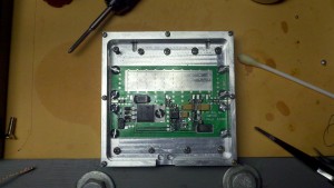
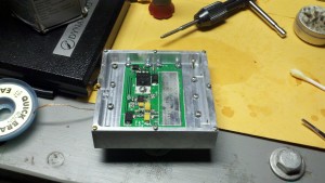
When I first began this part of the 902 W1GHZ transverter project, the module is not yet put down on the board, the board is populated with all the components and also has been fitted into its aluminum enclosure, as seen here:

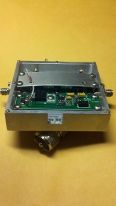
When finished, with the very generous help of my Elmer K4CSO, the driver amp looks like this (minus cover):

The SMA mounts were drilled, tapped and installed.  It has been plumbed for power, as noted by the wire coming off the regulator going to the external connector. The board, when finally set, used thermal grease on both the ground plane and underneath the module itself in order to mitigate as much heat as possible (actually, a great deal of the grease bled through the thru-way’s drilled into the board- care was taken to make sure the correct amount was smoothed over and used- one of the few cases of “less is more”).  The bar set across the top of the module (the module underneath, I grant you, is difficult to see) is used to make sure that the module stays flush with the board- also incredibly important for heat transfer.  Removing as much heat as possible is critical to the longevity of this module and I will eventually have to mount a fan to the underside- it runs that hot! Why go to all the trouble to build this if you aren’t going to take care of it?

Once the construction is taken care of how you see fit, which hopefully includes some manner of heat dispersion, one’s attention should turn toward the actual biasing of the module- the matters of voltage and current.  According to rfextra, the module should be calibrated and reviewed, “Around 4-5V, monitor the current when(sic) increase the bias voltage: at low RF input like – 20dBm, stop when current is about 1.4-1.6A.”  I didn’t have this information when we began to tune the amp- poor preparation on my part- and we simply ran out of time.  However, a conservative approach got us to nearly the same place the instructions did, so all was not lost.

After placing some current on the device, it did not self-oscillate, which is a great sign. This means there is no RF escaping somewhere to induce the device to oscillate itself. We started driving the device around -20dBm and stopped around 0 dBm. We got about 4.4 watts out at this point and were hesitant to go further without proper biasing instructions (people are claiming 10 watts out of this module at 12 volts- I’m not interested in running it that hard).  We did not pass one amp of current for biasing- which is not enough current as per the instructions, though we did hit 5.3 volts- which is beyond the upper end of the instructions I later received.  So, we are lucky we didn’t destroy the component, but it also looks like we aren’t going to get too much more out of it, either.  A little more tweaking will get closer to 5 watts, which is all I will need to drive the Motorola amp mentioned above. Of course, if I drive the big amp a little less, that’s not a worry, either.  I’m not looking to wring out as many “deebees” as possible at the risk of destroying what I’ve already achieved.  As it stands now, there probably isn’t much more tuning to be done and I am very happy with how the module turned out.

Now the question becomes one of how to attenuate the transverter output to feed the amp at around 0 dBm.  If it isn’t one thing, its another!

W7BAS 1296 MHz Transverter Arrival 8/7/11

Not one to sleep, Bruce, W7BAS, has been burning the midnight oil to bring us two new transverters to add to his current stable of 222 MHz and 902 MHz models.  This release is very much like a buying two bookends- Bruce has come up with a 144 MHz and 1296 MHz design (he is also working on another pair of transverters to be released soon- 432 MHz and 2304 MHz).  The 144 MHz transverter is, “very sensitive and quiet on RX. Better than -140 dBm.”  The 1296 MHz transverter  is “better than -135dBm on RX and quiet also.”  Both have an output of ~+17 dBm.

Pricing is as follows:

144 Transverter + Micro-Synth L.O. (user choice of 28Mhz/50Mhz I.F.) = $279.00 (both assembled); $249.00 (XVTR Kit Micro-Synth Assembled)

222 Transverter + Micro-Synth L.O. (user choice of 28Mhz/50Mhz/144Mhz I.F.) = $259.00 (both assembled); $229.00 (XVTR Kit Micro-Synth Assembled)

902 Transverter + Micro-Synth L.O. (user choice of 28Mhz/50Mhz/144Mhz I.F.) = $259.00 (both assembled); $229.00 (XVTR Kit Micro-Synth Assembled)

1296 Transverter + Micro-Synth L.O. . (user choice of 144Mhz I.F.) = $279.00 (both assembled); $259.00 (XVTR Kit Micro-Synth Assembled)

You will note the price increase; but you will also note that with the increased price you are getting one of Bruce’s very excellent synthesized L.O.’s.  This, in my mind, is a better bargain than he was previously offering and you’d be a fool to pass at this price.

Bruce will have these new 1.2 GHz and 144 MHz transverters available August 7, 2011. Order from his website Signalblox.

VK4ZQ’s Excellent Microwave Blog

Roy O’Malley, VK4ZQ, has put together what has to be one of the best blogs about microwaves I’ve seen.  Through his erudite postings, you can learn about his portable microwave setup, how to get on 10 GHz easily and how he designed his rover antenna setup (it’s on its own trailer).  His great attitude and enthusiasm really shows in the quality of his pictures and the text itself.  Good show!  Give Roy a read- you’ll learn something!

Driver amplifer enclosure

Got a friend to lend me his portable drill press so that I could mount the 5 watt 902 amplifier board in its enclosure.  After I drilled the pilot holes, I tapped them and everything fits together quite well.

Now, all that remains is figuring out where/how to drill the SMA bulkhead mounts (and drill, tap and then mount them).

W7BAS LO Review

There are many factors that determine good circuit performance.  Proper design techniques, careful part selection and the attention to detail when it comes to assembly of a device are the three chief concerns of any electronics endeavor.  But that is ex nihilo- upon what corpse is this creation to rest?  In the same way that bodies have dominate sides or particular faculties, so too does the enclosure around which an electronic creation is encased.  Microwaves are their own little creatures, after a fashion, and what you may find from one circuit board sitting on the end of a couple of attenuators, conjoined with the DC blocking adapter which then leads into the spectrum analyzer, can be completely different than what such a board, similarly attached, might produce when it is enclosed, and enclosed in the proper way.

I happen to know this through experience- which, so far as I know, is always acquired “the hard way.”  In my case, I was attempting to wire up my transverter boards to my radio in order to see if it was functioning.  I didn’t have any luck hearing any signals, mainly because I wasn’t properly set up to hear any, and in any case, it was late, I was tired and one loose wire screwed everything up when it energized the transmit section with the wrong voltage.  I caught it pretty quickly but not before the white smoke escaped and I thought I had blown it up.  What a way to go to sleep!

So, I contacted Charles, K4CSO, and asked if he could help.  He graciously offered to see what, if anything, was malfunctioning with the transverter.  As it turns out, apparently nothing is wrong and I caught the overvoltage in time.  What was more interesting was  the performance of the W1GHZ LO.  Paul writes in his paper “902 MHz Transverter for the Multiband Rover,”

“The revised LO board with the combination filter works very well, with a 756 MHz output of +7 dBm, perfect for driving a mixer. The spurious outputs at 36 MHz away on each side are at least 30 dB down, and all other frequencies are more than 40 dB down except for a strong second harmonic at 1512 MHz.”
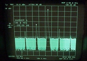
In this photo, you can see the harmonics Paul was talking about, and yes, they are ~36MHz spaced from the center frequency and approximately 30 dBc as mentioned.
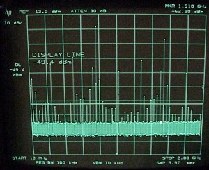
Above is a photo of a sweep from 10 MHz to 2 GHz.  As Paul stated, the LO works as advertised.  But it is dirty.  Very dirty.  I was curious as to why this is the case, as I would like to eventually use this transverter with some power- garbage in and garbage out- and being a good amateur I would prefer to have a cleaner signal.  As I understand it, there is some overlooking of dirty signals the higher one goes in the bands- since no one is there and construction techniques being what they are, you aren’t likely to have a complaint when you are one of the few on the band!

However, that doesn’t answer the question of why there are so many harmonics.  Charles informs me that such even spacing at such a small frequency multiple (in this case, ~36 MHz) is very likely to be the 36 MHz crystal oscillator that is located on the LO itself. One guess is that the signal out of the oscillator is getting into main LO signal via the large ground plane on the bottom of the board.  It’s possible, too, that somehow the signal is getting mixed in one of the MMICs.  It is also possible that once enclosed the transverter may act differently.  In any case, I wasn’t terribly concerned with this until we put the W7BAS synthesized LO on the analyzer.

Confession time:  After reading my post regarding building my W1GHZ transverter, W7BAS offered to send me one of his LO’s, gratis.  I accepted.  I’ve decided to write this review about it and will include the W7BAS LO inside my transverter.  This review wasn’t solicited by giving me a LO and is completely independent of whether I got it freely or not.  I realize I’ve spoken about the W1GHZ LO at great length; you will have to forgive my lack of brevity in this review in the interest of full disclosure- which whether I paid for something or not would, I hope, be the same.  Also, the reason I am rejecting the W1GHZ LO isn’t because it doesn’t meet its published specifications- its because I’ve now got something that is much better.  It should also be pointed out that there is the caveat regarding whether this LO was enclosed or not- as mentioned at the beginning, whether some board was enclosed or not so could make a significant difference in the measurements that are collected.  As both were tested in the same way, one could argue that neither has a testing advantage over the other and would perform the same way in the same enclosure.

From what I’ve read, many people originally didn’t care for synthesized local oscillators because the phase noise was simply too high.  However, cost is always the main issue, and with synthesizers lowering the cost of microwave LO’s, the telecom industry moved towards this technology without hesitation.  This technology was cheaper and cooler to run.  With less heat meaning less waste, the cost goes down further.  While it might not have been at the time the most elegant solution, it was certainly the most expedient one.  Today, the phase noise continues to decrease and there is now wide acceptance in microwave circles, and elsewhere, of synthesized LO’s.

The W7BAS LO drew 40 milliamperes and is designed to take a 12 volt source of DC power- something the W1GHZ transverter is sorely lacking.  When put on the spec an, the frequency readout was incredible- 755.999 MHz.  This is probably intentional (the goal was 756 MHz)- certification shops tend to always under certify some device by just a smidge in order to account for voltage/power differences between the lab in which the item resides and the actual shop that does the certification (and I believe there are other reasons for this in which I am not competent to articulate; I could very well be wrong about this point and could have misinterpreted what I’ve read, so do please be aware of this).

Like the W1GHZ LO, the W7BAS device also had a second harmonic around 1510 MHz. The main signal output was around 8.5 dBm, as sent from W7BAS.  The second harmonic, unlike the W1GHZ second harmonic, was not just -30 dBc down- it was more than -60 dBc, as seen in the following photo:
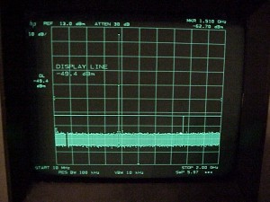
You will also note the lack of harmonics.  This signal is, in the vernacular, “so fresh and clean” that it honestly couldn’t be practically better.  If it was, I’m not sure what benefit would be achieved (this photo was a 10 MHz to 2 GHz sweep).  Other than the second harmonic, there are no other harmonics of any consequence.  This means that the signal made by the transverter wouldn’t be all over the spectrum (especially with the amplification issue looming in the future) and would be quite clean.  In fact, it may be one of the cleanest on the band!

Considering the purity, but not in any religious sense, of this LO how could you not switch teams from the W1GHZ to the W7BAS?  Admittedly, there is a price difference. The assembled W7BAS LO costs $89 bucks plus shipping.  The other LO costs, all components in with the board and you assemble it yourself, around $25-30 bucks depending on shipping and parts costs.  Why the price difference between two items that do the same thing?  Well, look at the pictures.  One does its task much better than the other.  Will it matter in the long run which you use?  I cannot say as I cannot speak to your needs or environment.  Nevertheless, I would argue that the extra dollars are worth it because you have a cleaner and more precise signal.  With a more precise signal, the less likely it is you have to tune around due to frequency drift, and the less of that you have to do should equal less frustration and effort.  Who doesn’t love that?

I wholeheartedly endorse getting on the synthesized LO bandwagon and can’t think of a better driver than W7BAS.
VK3XDK 3.4 GHz Transverter Available

Graham recently announced his long awaited 3.4 GHz transverter is finally available from him for $150 AU plus shipping.  You can find more information at the following web address:

http://www.vk9na.com/Transverters.html

Please note that the website has not yet been updated to reflect that the transverter is available; also, you may find Graham’s email address located under the blue “Contacts” heading about two-thirds down the page.  Please contact him for more information.

The MIT Radiation Laboratory Series

If you are interested in a piece of microwave history, one could look no further than the RadLad series of papers.  This is an interesting bit of arcana- mainly because the research was released into the public domain, via MIT.  However, there appears to be some corporate skullduggery at play, and the files were no longer hosted by MIT and have since been privately published.  I’m not sure how something that once was public domain isn’t any longer- in any case, that seems to be the issue here.  Grab the paper while you can.