How are you going to do it? How are you going to build a 902/3 MHz. transverter so that you can activate a little used band and thereby increase your score in the VHF contest in which you are competing? Why would you do so? Since it isn’t a world wide allocation, there isn’t going to be any interest from abroad and very few US bound hams populate the band. More than that, how would you approach such a project if you had never done anything like it before? Where do you learn to be creative in your solution to your radio goal without having the requisite experience or training? Of course, if you had the experience, you’d have learned how to be creative in your answer about building a transverter and the question would be moot.
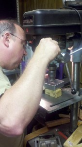
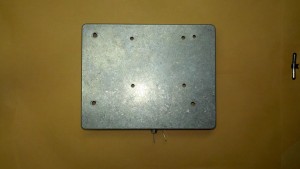
But it isn’t moot for me and building my transverter is still an ongoing process. I don’t have a drill press, for instance. If I did, what I could do with a couple minutes worth of measuring and using the right tool would save me weeks of time. I can’t journey up to see Charles but every so often and he can’t see me every day, either. So, you do the best with what you can regarding scheduling. Putting one of these together isn’t hard in terms of doing the soldering. But, this isn’t a case of having the right wire strippers and being able to make progress. When you use the wrong tool- impatience and a hand held drill in my case- you won’t get the clean results that you had previously (please note, the enlarged holes are the result of one wobbly bit which offset all other measurements. Use the right tool for the job!).
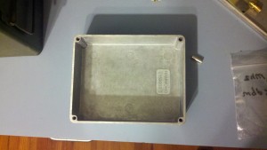
Even so, it isn’t the biggest mistake I’ve ever made. I decided on the Hammond box to be the enclosure for both the LO and transverter board. The LO doesn’t need to make any external connection through the wall of the box, so I put it in first (on the proper stand offs).
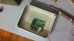 Of course, the LO had to be modified somewhat to interface with the W1GHZ transverter. The SMA connector was desoldered from the LO and new power lines and toroid were installed.
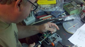 In place of the SMA connector from the LO, coax was installed which will directly interface (that is, be directly soldered) with/to the transverter board. Here this build gets down to brass tacks- the questions about how to engineer a 902/3 MHz. W1GHZ transverter now relies upon what sort of radio is going to be used, what sort of sequencer is best to run everything (I picked the TCK model from Down East Microwave, based on the coax relays I am going to be using- there are cheaper ways to go) and how best to interface all of these choices into one singular device. There is more to be said about this project, but can’t be without the proper pieces coming into place. Stay tuned!
In other news, it may behoove the reader to use a bit of coax shield in the trench around the lid of the box. It helps to make contact between the lid and the body and will perhaps help you avoid producing or being receptive to RFI.
